Modding the GekkoScience Newpac USB Bitcoin miner for performance
Introduction
I originally was into mining BTC back in 2009-2012. First on CPUs, and then on FPGAs when they were the newest technology available. Soon after ASICs came into being, places with better trade links to Asia and cheaper electricity took over, and my participation in mining ceased.
Now in 2023, I decided to get back into it. My primary reason was curiosity of how things have changed, and what improvements have occurred, and what it takes to set up a mining operation nowadays. Beyond that it is nice to actually contribute to the Bitcoin network. I have always run a full node, since the beginning to present day, but actually doing proof of work is another level of contribution.
The biggest change of course, is that mining is no longer profitable for the individual hobbyist. You need to be mining as a business, and treat it as such.
For the hobbyist, the best option is what the community generally calls "lottery mining". This is when you do solo mining expecting not to be profitable, or even break even. Rather like paying the lottery, you spend some time and resources, and if you strike it lucky, you can get a whole block reward (as of 2023, 6.25 BTC).
My ASIC Miner
I did not want to spend a lot, nor did I want something that will draw kilowatts of power. At the small scale you just can't compete with mining farms, so my goal is more low total cost and good GH/s efficiency, rather than generating enough hash to pay costs.
So with that in mind, I had a look at what second hand ASIC USB miners I could find on online auctions. USB miners originally were competitive, but with the growth of the mining industry there were rendered obsolete. Nowadays they are specifically marketed as "Lottery miners", and as training tools to understand mining, precisely because their breakeven is on the span of decades, if ever.
There are also people who bought these when they were profitable, and mined with them until they upgraded to keep up with profitability, so there is quite a good supply of used ASIC equipment.
As it happens, a GekkoScience Newpac ASIC miner was on auction. 23GH/s stock, using two of the "most efficient ASIC chip available", the BM1387. What also caught my eye was that the seller said "23GH/s+", and explained that the miner can be overclocked to 90+ GH/s.
That piqued my interest, and I ended up winning it for £65. A few days later it arrived in its own case with a little passive heatsink attached.
In my excitement, I realise I didn't actually take a picture of it upon arrival, so you will have to search for "Gekko newpac usb stick miner" on your favorite image search engine.
Software install and initial testing
Instead I immediately went to set up the software, and this is the first place where I noticed things have actually gotten worse since I last mined. Back then the stock binary package supported my FPGAs no problem. Just install it and off you went. This time however, it was not so simple. Before there was just cgminer, now there are others as well, they all support some ASICs but not others. To make things worse, seems cgminer has been abandoned upstream, and there are multiple forks of it with different levels of compatibility, functionality and bugs.
The GekkoScience ASIC miners are only supported on cgminer, so there are a few forks with support for them, all with different bugs. Getting one to just compile was a mission, and then I had to modify the code in order to make it compatible with new versions of bitcoind. Eventually I managed to beat Wareks fork into a usable state for my bitcoind version (v24.0.1).
Also FreeBSD support seems to be pretty much nonexistent. I have yet to get a version of cgminer with gekko support to build on FreeBSD, so for the moment I used my Linux Desktop to connect to my BSD box running bitcoind.
For those of you who don't need to hack at the source to get it to compile, the below should be enough to get you started:
apt-get install build-essential autoconf automake libtool pkg-config \
libcurl4-openssl-dev libudev-dev libusb-1.0-0-dev libncurses5-dev zlib1g-dev
git clone https://github.com/wareck/cgminer-gekko.git
cd ./cgminer
./autogen.sh
./configure --enable-gekko
# Insert any Hacks here if necessary to get to work
make
make install # Optional
Once the software was up and running, connected/as a solo miner, I could give it a try. With the starting frequency of 50MHz, the miner gave me 23.5GH/s as advertised.
The description said you can overclock the miner and run higher frequencies, so I tried to see how high I could go. Pushing above 100MHz the passive heatsink got very hot (enough to burn your fingers), and the ASIC reset.
To carry on my testing, I positioned a saucer of water just below the PCB, so the heatsink was partially submerged.
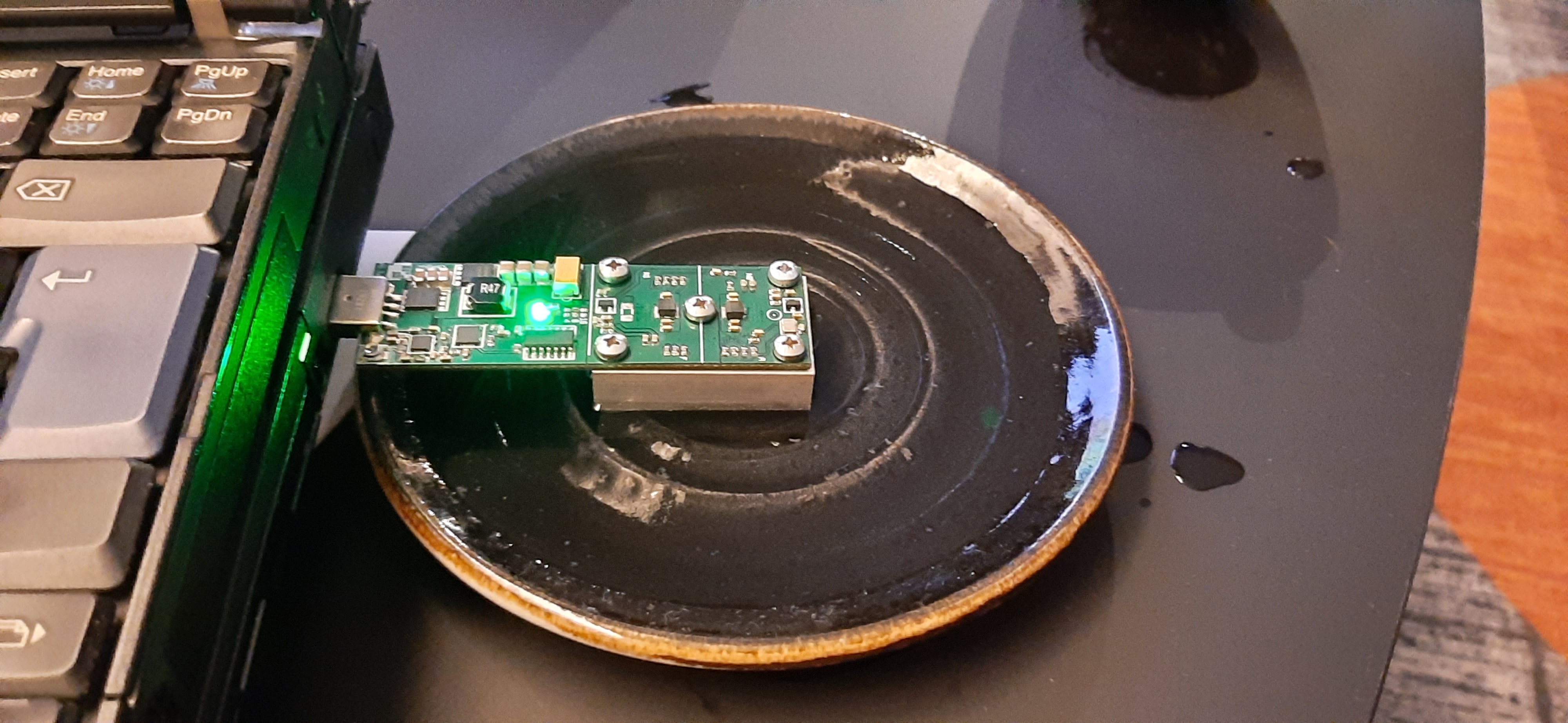
And so was born probably the only instance of an semi-immersion water cooled newpac miner! Realistically this was not a long term solution, but the pool of water kept the miner cool enough to let me briefly drive the frequency even higher to see what it could do. On my laptop USB port, with the liquid cooling, I was able to hit 350MHz, with a hash rate around 80GH/s.
This proved to me that the miner (a) is in working order (always important when buying second hand), and (b) the description about it being overclockable and capable of more than 23GH/s is true.
The only question now, was how much you could overclock it? Before we can find out, we need to build a system that can support the power and cooling requirements.
The supporting hardware
In the interest of keeping costs low, and because I really was not sure how much is "enough" power and cooling, I decided to build the support hardware out of whatever parts I had in my junk box.
This consisted of:
- An AMD Athlon (T-bird) Coolermaster Aluminium CPU heatsink
- A USB 5.25" external case (with damaged front panel)
- An Apple G5 centrifugal case fan (left over from my ATX G5 case conversion)
- The external cases original Power supply (which provided both 5V for the miner, and 12V for the fan).
The T-bird heatsink was originally for the CPU so named (back in 2000! I really do keep a lot of junk!), which was required to dissipate about 80W of heat in its original use.
The Apple fan is a good quality ball bearing fan, and can push a lot of air when running at full power. These two combined should be more then enough to keep our miner cool, so the first job is to adapt the heatsink to the miner.
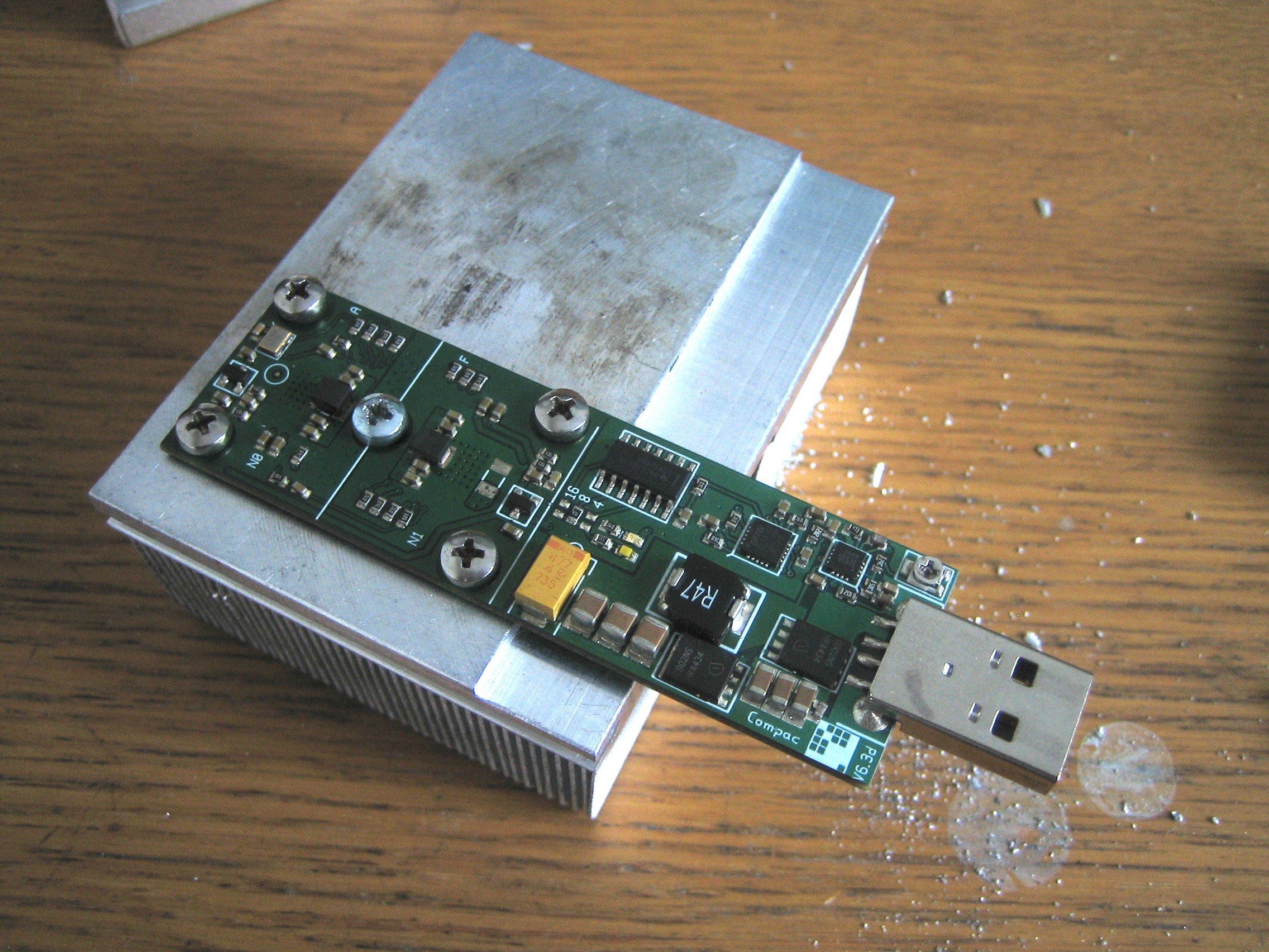
The miner test fitted after we had drilled and tapped five 3mm holes, matching the locations on the miner:
Next was to position and cut holes in the aluminium case to fit the heatsink and fan. We wanted to make the case act as a secondary heatsink, so the coolermaster is screwed directly to the case. The mounting points for the fan were used to mount the heatsink straight to the case, which effectively created a tunnel with the fan blowing it one end and exhausting straight out of the case on the other.
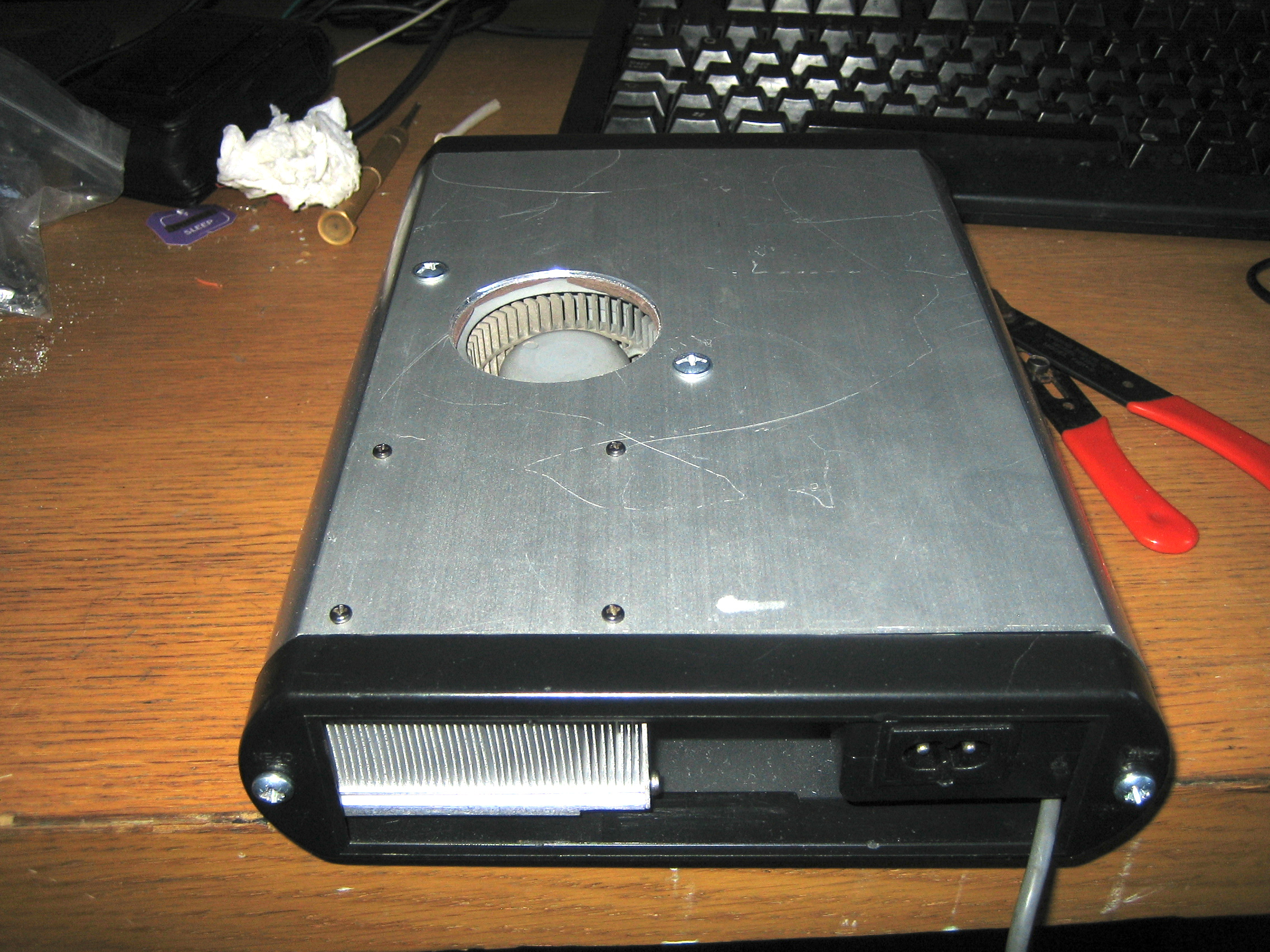
Likewise a hole was cut for the fan intake, so that it get unrestricted cool air straight into where it is needed most, and the mounting holes came soon after. The PSU was small enough to be mounted in the case as well, so we mounted it to the other side, held in place with screws. On the photo below you can see the intake hole with fan and rubber seal mounted.
Here you can see inside with everything mounted:
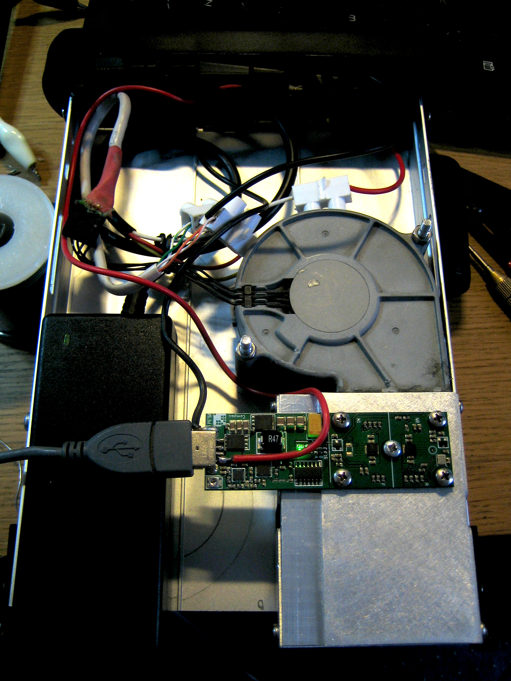
We have sanded down the heatsink surface to clean up the years of grime that had accumulated, then we deliberately offset the miner to one side so there is space for a second one if desired in future.
The PSU provides 2A at 5V, and 2A at 12V. This is more than the 500mA provided by the USB spec, so should be able to sustain higher clock speeds.
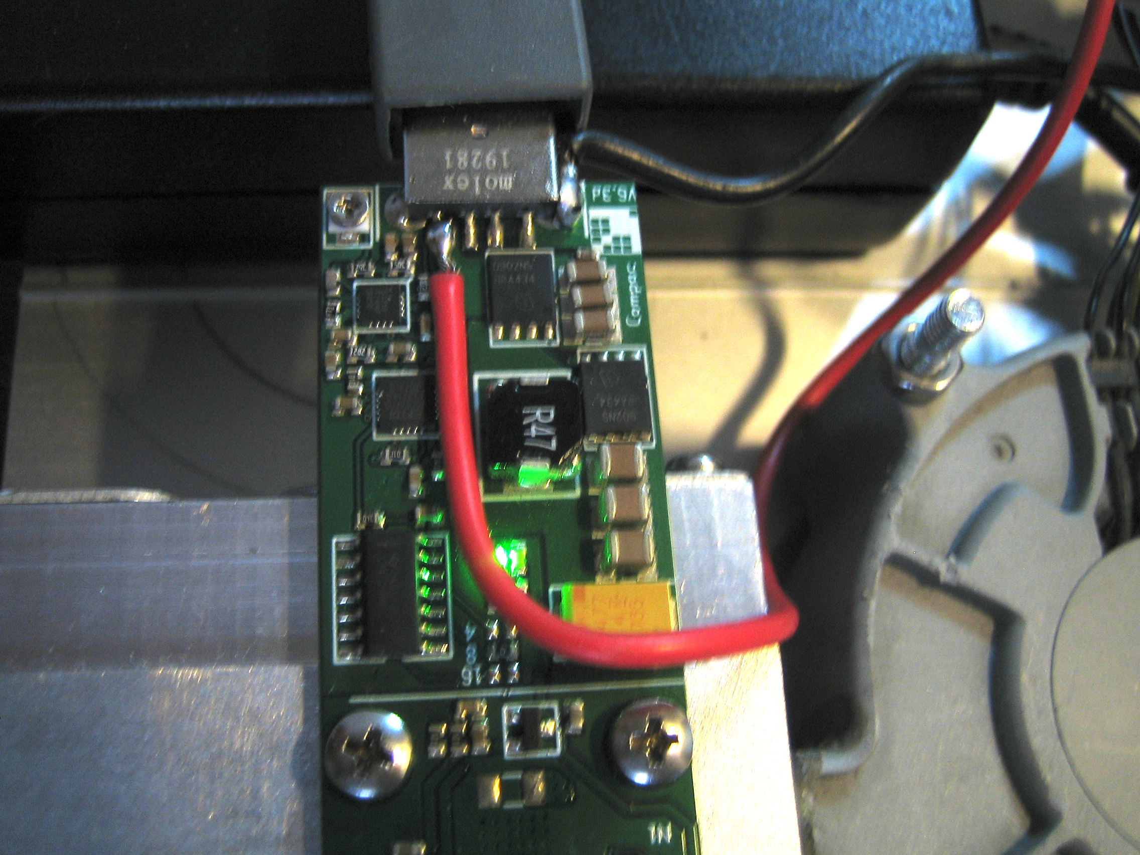
To deliver this current with minimal losses, I decided to dispense with the USB power connector, and instead soldered the power cables directly. This was easy for GND, but for the 5V line it was fiddly to do without shorting out the contacts.
Note to the GekkoScience HW engineers if you are reading this: Please provide some pads on your future PCBs to allow us to solder cables directly. At least provide it for the positive supply. We can get GND from the USB connector and the data lines can be handled by special "data only" USB cables you can buy, but the 5V line is a different matter.
Anyway, job done to the best of my ability, and will work as long as the wires are not moved too much (thankfully it is all bolted down and encased):
Benchmarking
So with the system set up, we fired up cgminer and started doing test runs, ramping up the max frequency at each run. Each run would last 15 mins, and we would take the "5mAVG" presented by cgminer at the end of the run.
The results are as follows:
MHz,	GH/s
 50,	23.5
100,	40.9
200,	44.9
300,	67.2
400,	82.5
500,	112.9
600,	134.9
650,	147.5
662.5,	150.8
668.75,	147.8
675,	144.9
681.25,	125.2
693.75,	28.32
700,	0
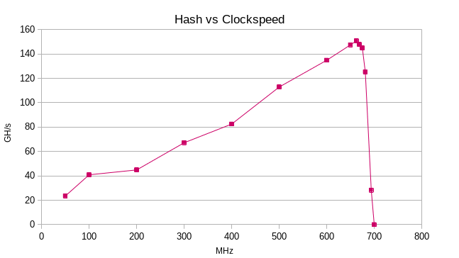
At our start of 50MHz, we are getting the approx 23GH/s that the miner was advertised at. However we are able to ramp the speed up all the way to 693.75MHz.
It is noted that the maximum clock speed does not correspond to the maximum GH/s, the miners hash performance actually tops out at 662.5MHz, and goes down from there. At 700MHz we don't even manage to run for more than a few minutes before the ASIC resets, so it is marked as '0', and we tested no higher.
Our best performance was 150.8GH/s, which is quite an improvement over the stock, and quite a bit higher than I expected it could reach. However the failure mode is odd, where the clock speed increases but the hashes decrease. I noticed that this was due to more failed work units (so on cgminer, our % success of WU was dropping).
Normally when I have seen this kind of "fuzzy" failure of electronic systems, it was either due to power or cooling limitations. Cooling was ruled out in this case, because (a) the heatsink is still only lukewarm to the touch, and (b) cgminer will detect when this miner ASIC gets too hot, and will lower the clock frequency until stability is achieved. We don't see this, rather we see a continuous ramp up of clock speed, until it resets.
So to me, this indicates the issue may well be due to power. First thing I decided to do was measure the voltage delivered, because quite frankly it is faster and easier than measuring the current. All I do is hook up my scope in data logging mode, and let cgminer ramp up the clock speed automatically until it resets. Results below:
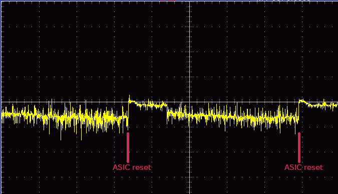
We started at 500MHz, and ramped up to failure. We zeroed the Y axis at 5V, with 1V division on the graph Y-axis. First thing I noticed, is that the 5V line is very noisy. Second thing that was noticed is the slow voltage drop as we ramp up. After ASIC resets the voltage jumps up to 5V again, then goes down from there. Once we start reaching 4V we get an ASIC reset.
This looks like the PSU is struggling to maintain the current draw. At some point beyond the max rated power draw, the voltage drops as the current increases.
Therefore the next thing we need to do is find out exactly how much current is being drawn. This is a manual task involving an ammeter and me launching cgminer with different clock speeds. Results below:
MHz,	I (Amps)
50,	0.64
100,	0.4
200,	0.72
300,	1.06
400,	1.44
500,	1.87
600,	2.36
662.5,	2.52
668.75,	2.53
675,	2.5
681,	2.48
693.75,	2.46
700,	0
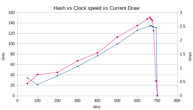
I overlaid the current draw on the right Y axis on the graph above (in blue). First thing I noticed is that the max current draw before reset was almost 2.5 Amps, 0.5 amps more than what the PSU is rated for. It corresponds to the max clock speed we reached without failure, but as seen in the graph, the hash rate drops faster than the current draw, indicating a loss of efficiency towards the top of the range.
Either way, it looks like we are hitting the limits of our power supply, so it needs to be replaced in order for us to push higher limits.
Easiest way for us to do this is to replace the PSU with a computer ATX PSU. As it happens I have some of them in my junk box, and I picked out one that provides 16A on the +5V line. More than enough power for this requirement.
With the new PSU quickly cobbled together for testing, we do some more runs. This time we did 1hr timed runs, with the following results:
MHz,	GH/s
693.75,	153.5
700.00,	156.7
706.25,	153.4
712.50,	110.3
718.75,	152.6
725.00,	36.68
731.25,	0
750.00,	0
This time we were able to break 700MHz, and (briefly) run at 725MHz before we started getting errors. The runs that did not end in failure were run for a full hour, and the average hashrate noted. Interestingly the highest average was at 700MHz. Any higher and it dropped off, until we get ASIC resets again.
This seemed to be due to the amount of successful "work units" (WU) submitted on CGminer. CGminer provides a percentage value of work units that were successful. Failures are due to miscalculations on the ASIC itself, and are rejected. You want as high a percentage as possible, otherwise you are just wasting energy making incorrect calculations.
Cooling and Power are still within parameters (the heatsink barely gets warm), so in my mind there are possibly two reasons for this:
- Limitations of the silicon
As with overclocking any chip, be it a CPU or ASIC, there comes a point where the silicon cannot keep up with the clock, and you start getting errors. In my case that seems to be 700MHz. I looked around for the datasheet for the BM1387, with no luck. The best I found was the BM1385 datasheet, which is a generation older. According to that, the internal clock is capable of going to 1GHz. It is likely that the more efficient, newer chip can also go that high (however CGMiner is limited to 900MHz). This does not mean our chips can reach that speed. Like most ASIC companies, there is always some percentage of defects in the chips. The ones with no defects go to the top-end equipment and they probably can run at 1GHz all day long, and ones with minor defects that still work get sold cheaper for less demanding tasks.
It is possible the chips used in the Newpac are from the "minor defect" batch, which is no bad thing. It makes the miner cheaper, and for the original specifications the chips were perfectly fine. It is only if you push the miner beyond its specs that you get issues. This would also mean that different Newpacs will have different max clock speeds, depending on the nature of the flaws in silicon. My one can reliably run at 700MHz, other peoples may be able to go higher or lower. - Limitations of the onboard DC-DC converters
While perusing the BM1385 datasheet, I noticed that the chip max voltage is just under 2V. This means our 5V is being stepped down further on the board itself. It is plausible that the onboard DC-DC converters cannot supply enough current to go beyond 700MHz. The reduction in valid hashes with increasing clock rate, followed by ASIC resets are very similar to the failure mode we saw earlier when our PSU was the limiting factor. If this is the case, then I expect 700MHz is the limit any Newpac can handle, as the onboard converters cannot feed the chips with more power. Unfortunately not much can be done about this that does not involve major surgery to the chip. If you got the skills to do such work, you are probably better off just buying a different miner, or making your own (perhaps this Bitaxe project which I just found while researching the "BM" series of ASIC chips might fit the bill?).
Possibly you can try over-volting the miner in the hope that you can eck out a few extra GH/s, but then you run the risk of burning something out, all for a little extra hashes that will not really impact your profitability in a lottery miner.
So as far as my Newpac is concerned, 700MHz seems to be sweet spot for max hashrate. It is already far more than I expected I could get from this card. So now we are going to run at this speed going forward, and check the stability and longer term hashrate.
Long term running
Sustained Hash rate
So having got the system working, next thing I did is write a quick perl script to connect to the cgminer API and pull in the current hashes/sec value (5 and 15 minute average). This was then plotted on my MRTG system.
The results:
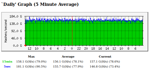
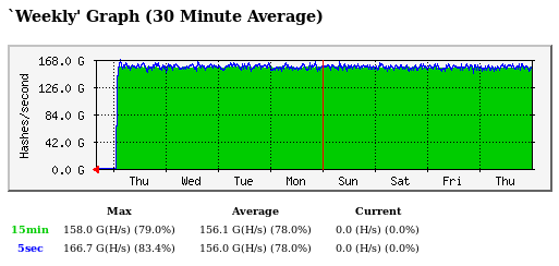
We are averaging around 155GH/s over a 24hr period, and 156GH/s on the weekly period. Unfortunately Sod's law came into effect and we had a power cut at the very end of the 7 day test, affecting the average. Either way, the system is proving stable and reliable at 700MHz. Considering this miner was advertised at offering 23GH/s, stable operation at 156GH/s is almost 7 times the expected performance. An impressive improvement, in my case using components I just had lying around.
Sustained power draw
Now that we have our stable clock speed, we can investigate what is our current draw is. The last time we measured the current we could not reach 700MHz, but based on the data we got, I expect it to be between 2.5 and 3A.
So we hook up our multimeter and measure again. At 700MHz we clocked a current draw between 3 and 3.1A. At 5V this gives us between 15 and 15.5W of power draw.
However I then realised the USB port itself can provide between 500mA and 1A of power, so the next step was to connect the miner to a hub that provided no power, just data, and then measure again. This time we measured 3.82A, meaning we were drawing around 720mA from the USB port itself.
Interestingly while doing these measurements, the ASIC was not stable at 700MHz. After a few resets cgminer settled on 687.5MHz.
This was not completely surprising. There are two ways to measure DC current:
- Using an active circuit with hall effect sensor.
- Using a shunt resistor in series with the circuit, and measuring the voltage drop across the resistor.
The second is the more common method, and it is in fact the one used in most ammeters. The lower the resistance of the shunt resistor, the less of an impact it has on the circuit, but the smaller the measurable voltage drop (increasing noise, and requiring more sensitive detectors).
I use my multimeter to measure current, and it has a built in shunt resistor of unknown value. Whatever it is, it may be a high enough resistance to introduce a voltage drop in the circuit high enough to trigger an ASIC reset.
It also means the current indication is not 100% accurate, however it is close enough for our needs, which is to work out approximate power draw, and see if we can find a more suitable PSU that will fit in the case.
Running on FreeBSD
So we got our miner running, but at the moment I run it on my Linux desktop. Having 400W of machine sitting near idle 24/7 to run a ~20W miner is not efficient. On the flip side, I have a FreeBSD server that runs 24/7 anyway, so it makes the best sense to use that.
We tried the following methods so far:
The FreeBSD "Linuxulator"
FreeBSD abstracted away their application binary interface (ABI), meaning you can emulate different systems on a single machine as if they were native. The FreeBSD handbook discusses how to enable the Linux ABI layer (Called the Linuxulator, after which you can run full Linux distributions in a chroot environment.
This seemed like the first port of call, as it requires no changes to the cgminer code. So So I followed the handbook, and the result speaks for itself:
# uname -s -r -s -v -o
Linux 3.17.0 FreeBSD 13.1-RELEASE-p6 GENERIC GNU/Linux
An odd mix I've never seen before, a Frankenstein of Linux and BSD! The rest of the task is almost the same as mentioned for the Linux compile, you even have "apt" to install all the libraries you need. The compile went smoothly and cgminer loads up just fine when USB is not enabled.
Unfortunately while software compatibility is spot on, interfacing with hardware is a different matter. In our case after we compiled with USB support, we could not get cgminer to interface to the USB subsystem:
libusb_init() failed err -99 [2023-05-31 19:52:48.667] libusb_init() failed
37498 Segmentation fault      (core dumped) ./cgminer
After a few more futile attempts, we gave up. Unfortunately this method won't work for us. While the ABI supports Linux, the kernel is still FreeBSD, which precludes interfacing with the USB subsystem.
Compiling on FreeBSD
This likewise looks like a dead end. A query on the FreeBSD forums likewise shows a lack of progress on the matter, while the bugzilla bug report was closed due to upstream being unmaintained. I had a look at the code myself, and unfortunately it isn't just the code, the entire toolchain is very Linux specific, it would require a lot of work to change, and I'm not sure if it is worth it for this particular project.
Using Bhyve (virtualisation)
Also looked into using Bhyve to run a Linux VM on the server. This is possible, but as I found out, I can't do USB pass through. I can pass through a PCI card, so I could pass the entire USB controller to the VM, but that would break the other stuff connected to the server, and there are no free slots for another USB controller card, so this is a dead end as well.
At this point, I just don't think there is any way of running this on my server, so giving up on this path for now
Update: October 2023
So we have been running with the ATX computer PSU up until now, which is bulky, messy and overkill for the system, so decided to change it. First I found an old IBM thinkpad charger with a broken barrel connector. This will put out 65W of power, but unfortunately at 18V, which is a bit too high for our needs. Therefore I bought a 15A DC-DC buck converter to step the voltage down for us. Here it is installed, with the AC adapter's cover removed so we can solder new wires to it, and drill side holes for mounting.
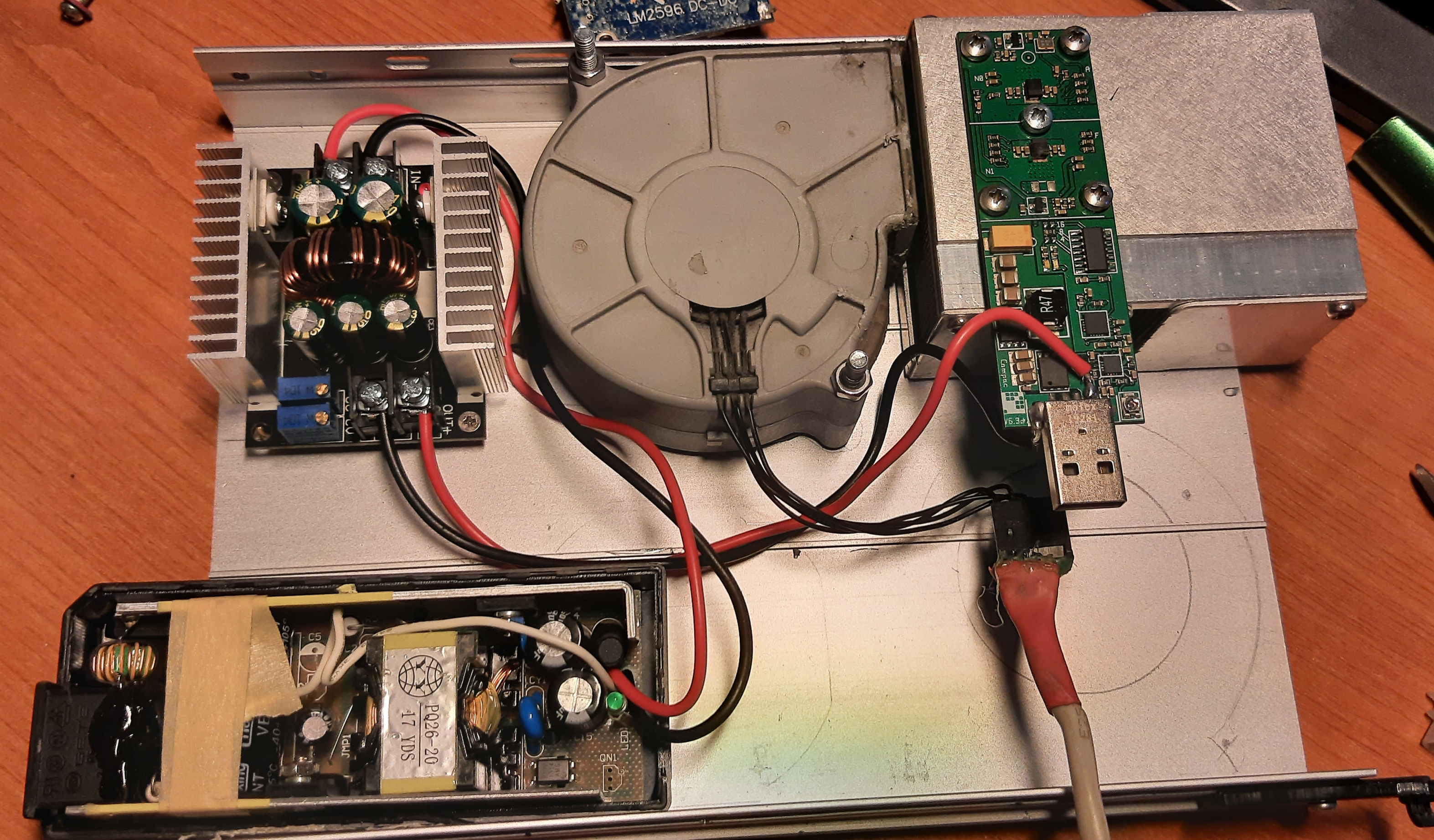
With that all working, the next step was to do something about the fan. 18V is too high for that too, so I rummaged around my junk box and found another low power DC-DC converter. There was some space on top of said fan, so I placed it there:
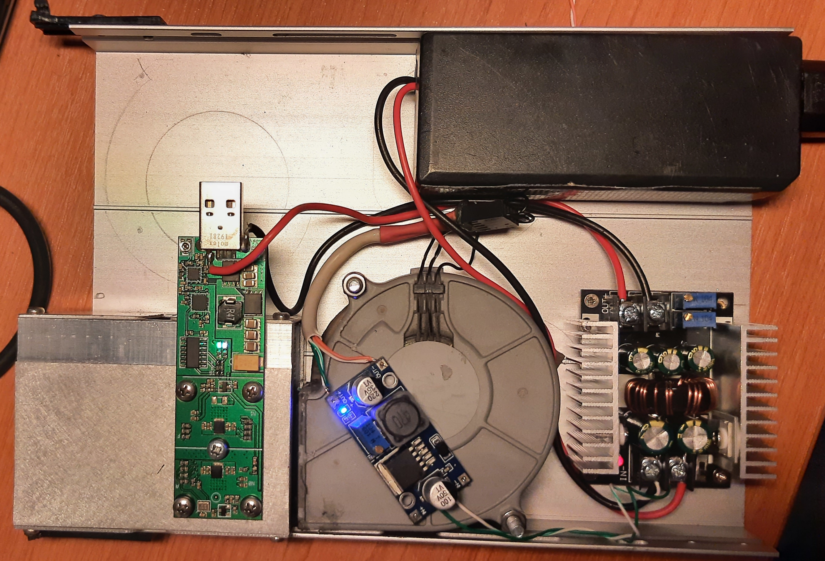
This setup has the advantage now that I can control the fan speed by altering the voltage without affecting the miner. As such I lowered the voltage down so that there is a good balance between noise and cooling. In addition the PSU is now within the miner case, so the entire system is a single unit without any wires visible (except for USB and power at the back). Much tidier!
Overvolting
Now that I have 15A of 5V power to play with, I figured I could try overvolting the miner to see if I can get higher clockrates without issues. I found the manual online (Copy here) which had a section on overclocking. Interestingly it also had a power table, telling us the power draw (in Watts) at certain speeds (only up to 200MHz though). As we know the system runs on 5V we can calculate the current, which will allow us to compare their dataset with ours for matching data points. Their data is below, with calculated current:
Speed (MHz)	Power (W)	Calculated Current(A)
100		2.645		0.529
200		4.662		0.932
300		6.795		1.359
Compared to our data, at 100MHz we are within ~0.1A , at 200MHz we drift apart further (~0.2A) until at 300MHz we are ~0.3A apart. Still the deviation is within my expected margin of error, so it looks like we are in the right park when it comes to power draw. Unfortunately they did not go beyond 300MHz, which may have something to do with their ability to keep the miner cool.
Anyway, back to the overvolting. The manual tells us that we can twiddle the potentiometer to change the voltage, but tells us nothing about by how much does the voltage change, which I didn't like. All it said was that you risk voiding your warranty if you do this (understandably). So first thing I did was measure what the voltage across the potentiometer was, which was 0.18V in my case. Twiddling the potentiometer gave us between 0V and 0.35V (turn clockwise to increase, anti-clockwise to reduce voltage).
This voltage range initially made no sense, as the BM1385 datasheet gives a min/max working voltage of the 0.6V to 0.8V (and I expect the BM1897 would be similar). The best guess I have come up with so far is that there is a 0.5V base voltage, and this potentiometer does "fine tuning". A range of 0.0V to 0.35V would give us a working voltage of 0.5V to 0.85V, which is just a bit on either side of the min/max of the chips. Allows mild overvolting without risking burning out the chips completely.
Having worked this out, I started benchmarking the maximum frequency I could reach at each voltage level. This was gauged by changing the voltage, running cgminer and seeing how high the frequency gets until we get an "ASIC Reset" error. Results below:
Voltage		Freq(MHz)
0.00		575.00
0.10		681.25
0.14		693.75
0.16		700.00
0.18		706.00
0.22		725.00
0.24		731.25
0.25		737.50
0.27		743.75
0.30		743.75
0.33		737.50
0.35		737.50
Conclusion
First thing I discovered is that upping the voltage to the chips does not help us much. Even at max overvolting we were nowhere near the 900Mhz that cgminer can clock this chip, let alone the theoretical 1GHz that the datasheet says you can do. We notice that above 0.3V we had no improvement in max frequency. If we assume 0.5V base then +0.3V would give us the chip max of 0.8V. It is possible that the onboard DC-DC converter is the limitation. Indeed I have noticed that the power supply on the PCB gets really hot during testing (and use). I mean like "burning fingers" hot, so it must be running at near its maximum. If I was to have the time and inclination I could try fitting some kind of heat spreader on this part of the PCB to aid cooling, however I am not sure it would net us much improvement.
Take into account that we are not talking massive gains here, and in the Bitcoin mining world, where most miners have to have "TH/s" specs in order to be viable, putting more effort into getting a few more GH/s is really not worth it to me. So I set the overvoltage to 0.22V, and started doing 12hr tests for average GH/s. The results:
MHz,	GH/s
700	155
706	156.4
712	148.1
So once again, going beyond a certain frequency nets us less GH/s, while consuming more power and heat, as such I've set my miner to run at 706MHz and will probably leave it at that. Still, it was fun to see how far I could push this little USB miner.


